|
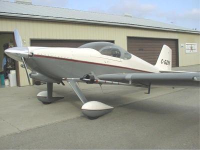
Vortex Generators on RV's |
|||||||||||||||||||||||||||||||||||||||||||||||||||||||||||||||||||||||||||||||||||||||||||||||||||||||||||||||||||||||||||||||||||
Over the labor day weekend, a
close friend, Gord Baxter and I crossed the country to attend the annual
Homecoming at the Van’s Aircraft factory. While there, we met
and talked to Mark Todd who has installed a set of vortex generators (VG’s)
on his RV-4. Mark is an enthusiastic supporter of VG’s and the
benefits that they provide. Performance enhancements such as lower stall
speed, clean break at stall, and better aileron authority at slow
speeds. The idea of installing VG’s for myself didn’t occur until
Larry Vetterman called me several weeks later. Larry retired from flying
and running a flight department, to build his high quality exhaust systems
fulltime. Larry has many thousands of hours of flight time in PA-18
Super Cubs with VG’s attached. He saw the great improvements that
they provided in the slow flight regime and has just installed them on
his own RV-4. Larry was impressed enough with the increased performance
that he acquired the rights to the VG kits designed by Paul Robertson of
Aeronautical Testing Services Inc. and wanted me to give them a try. Of
course I accepted and started to think of how I could actually measure
the performance differences that VG’s are reported to change.
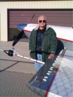
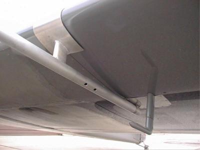
I was most concerned about recording actual stall speeds. Peter Hanna, a fellow RV-6 builder, had a swivel pitot head on a long boom that he was willing to lend me. Some slight modifications allowed me to mount the assembly to my wing without making any permanent changes or causing any damage. Gary Wolf of Wolf Heritage Metalworks Inc did some fine welding to ensure nothing would come undone. I flew several test flights and spent a great deal of time calibrating the airspeed indicator using three GPS ground tracks and GPS ground speed readouts as per Kevin Horton's page. I focused a digital Camcorder on the airspeed indicator with an intercom feed. Watching a 27" big airspeed indicator on my TV with a SVHS output makes determining airspeeds easy. I was dismayed to see the large non-linear error at the very slow speeds that I was planning on flying. The ASI was extremely accurate at all speeds above 100 knots but was reading almost 6 knots fast at 49-50 knots. I prepared the VG’s for a temporary installation and waited for a good flying day. I had done all the airspeed calibration tests at 8000’ pressure altitude and I wanted to do all the remaining flights in the same conditions. On November 30, 2000, I was able to perform top speed and stall tests without and with the VG’s installed. Initial results pointed to a decrease in stall of about 6 knots and a decrease in top speed of 3 knots.
I still wasn’t happy with my
ASI, so I installed another brand new one in parallel with the panel
mounted instrument. More calibrating determined that the new ASI
indicated 2.5 knots low at 150 knots and 2 knots high at 50 knots. I
also discovered that with the VG;s installed, I wasn’t able to achieve
a clean stall with the aircraft at the forward limits of the C of G. Of
course that meant running all the flight test components again. On
December 23, 2000, weather conditions were finally good enough to try
some flying.
A steel plate at 45 pounds
strapped onto the baggage floor placed the C of G at 72.68 aft of datum,
12.68 aft of the leading edge and 21.1% of chord. Gross weight at
takeoff was 1600 pounds. I was able to get clean stalls and the ensuing
break by moving the C of G aft. I performed all the stall tests with the
video camera focused on the new airspeed indicator. Three US gallons of
fuel (18 pounds) were burned to reach the practice area. All normal
loading stalls were completed from a starting speed of 70 knots and
power off, ball centered, and altitude maintained. Conditions were
8000’ pressure altitude and -15C.
The accelerated stalls were entered from 90 knots in a 60-degree
bank turning left. Three stalls were done in each configuration and the
odd number was tossed out.
I am somewhat surprised by the little “bump” in the data with the VG’s attached at the flaps 20 setting. I am also surprised at the non-effect that the flaps had on stall speed compared with the second table. A “bump” also shows up at the flaps 40 in the clean wing tests. Additional information on VG's can be found on a .PDF file at a NASA site. The observations from that report done a laminar flow airfoil showed the greatest difference in stall was on a wing with flaps at zero degrees. In my case the right wing dropped on all the tests with the VG’s attached. Displacing the ball to the left resulted in an incipient spin, which was recovered from with the appropriate control inputs. With the ball displaced to the right. The same wing drop was evident but not as aggressive. Little evidence of wing drop was
detected when the
stalls were completed with the VG’s removed. I think this relates to
the major trim change that I noticed upon installing the VG’s. I
fortunately had devised an adjustable trim tab on the under side of the
right aileron many moons ago and was able to adjust for trim neutral,
wings level flight. There is obviously something wrong in the rigging
that is accentuated by the VG’s. The original tests I ran showed
better numbers with flaps and VG’s installed. I suspect that was due
to the fact that I couldn’t get a clean stall with the elevator
authority I had at the C of G I was flying at resulting in a descending
flight path at a lower number. The top end speed runs were
re-done just before removal and my original findings were verified.
Following is the table of airspeeds. Conditions were 8000’ pressure
altitude, -15C, 9.4 US gallons fuel flow, 23.5” MP and 2400 RPM.
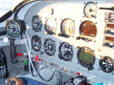
An interesting observation was made concerning angle of attack. I recalibrated the AOA indicator due to a memory lapse I had. I had forgot that the longerons are not parallel to the chord line. I adjusted the AOA markings and found that the clean wing stalls at approximately 19 degrees and the VG wing stalls at something greater than 20.5 degrees. The indicator would bottom (top?) out just before the stall. I think that this is why I haven’t seen much of a drop in landing speeds. My RV-6 sits at about 12 degrees angle of attack in the three point attitude. Any landing at 20 degrees or greater would put my tail wheel on the ground a long time before the main wheels. As far as the 19 degrees AOA without the VG’s, I thought that this wing should stall at about 17 degrees. Go figure! Keep in mind of course that these are findings for just one “homemade” airplane. I am somewhat dismayed that I didn’t achieve the results that RV-4’s seem to get. The somewhat shorter wing may account for some of the discrepancies. Terry Jantzi Terry Jantzi send me mail (only if it's nice) Larry Vetterman mail him, he sells the VG's
See more VG info and pictures See the Ontario RV site. for lots of RV's See
Terry's home site and the birth of an airplane |
|||||||||||||||||||||||||||||||||||||||||||||||||||||||||||||||||||||||||||||||||||||||||||||||||||||||||||||||||||||||||||||||||||